
 English
 русский
 Español
 عربى
عربى 中文简体
中文简体
WE ARE HAPPY TO SOLVE
PROBLEMS FOR CUSTOMERS
learn more >
Manufacturing Insight
Inside the Manufacturing of a Decanter Centrifuge: Bowl Engineering, Material Selection and Production Standards
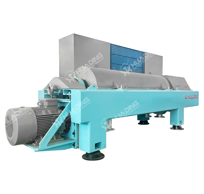
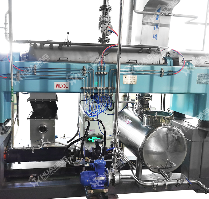
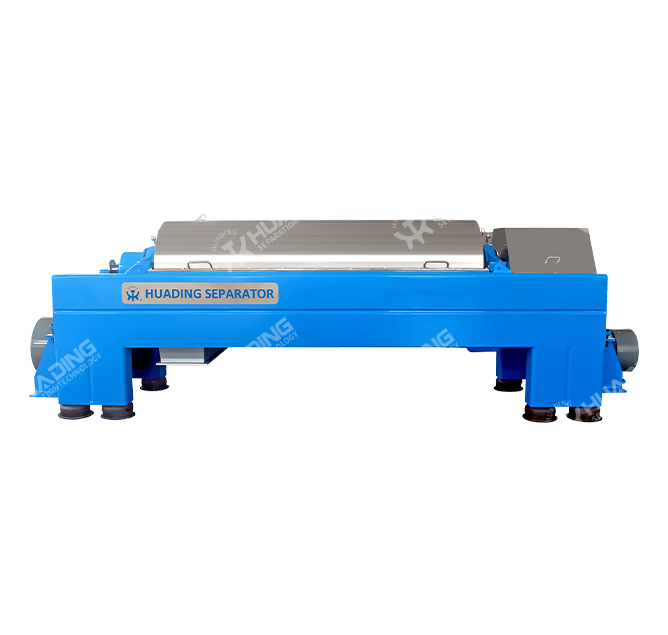
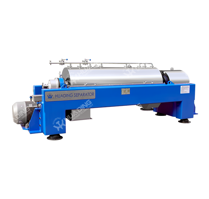
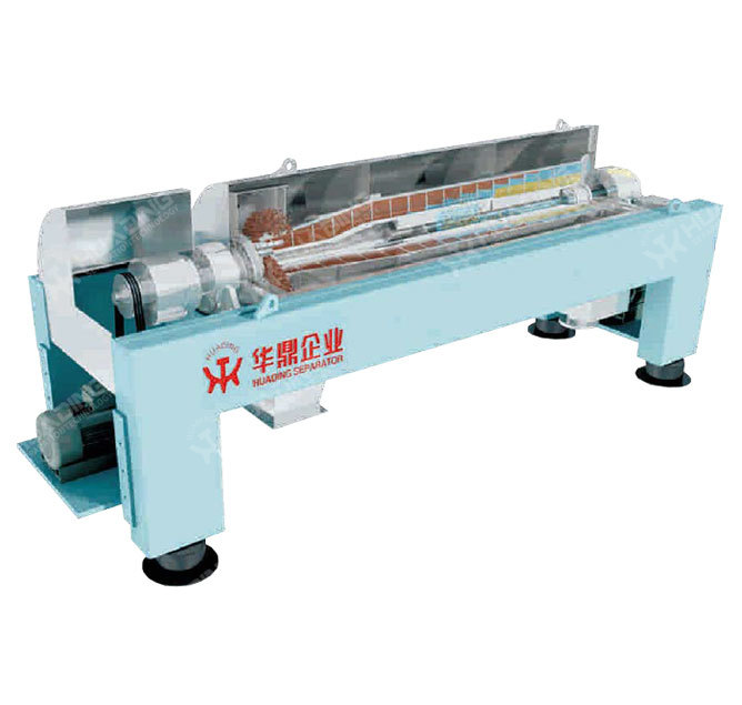
Every decanter centrifuge that leaves a production workshop carries hundreds of small engineering decisions inside it. Wall thickness of the bowl, the pitch angle of the screw conveyor, the alloy grade chosen for the differential gearbox — none of these details are visible to an operator standing at the control panel, yet they determine whether a machine will run for fifteen years or fail within a season. This section moves away from the general working principle of a decanter centrifuge and instead looks at the equipment from the manufacturing floor: how the bowl is machined, how the drive system is matched to the process load, what raw materials are used, and how factory-level quality control shapes long-term reliability.
Precision Bowl Machining
The horizontal decanter centrifuge bowl is turned on CNC lathes to tolerances measured in hundredths of a millimeter. Any deviation in roundness translates directly into vibration once the bowl reaches operating speed, so concentricity checks are repeated at multiple stages of production rather than only at final assembly.
Screw Conveyor Balancing
The screw conveyor is dynamically balanced together with the bowl as a single rotating assembly. This joint balancing step is what allows the differential speed between bowl and screw to stay stable across the full speed range without generating harmonic vibration.
Material Traceability
Duplex stainless steel plates and forgings used for the bowl, screw hub, and conveyor flights are batch-tracked from raw material certificate through to final machining, so every finished decanter centrifuge can be traced back to its source material heat number.
Wear Protection Application
Tungsten carbide tiles or ceramic inserts are bonded onto the screw flights and discharge ports in a controlled workshop environment, since inconsistent bonding at this stage is one of the leading causes of premature wear-part detachment in the field.
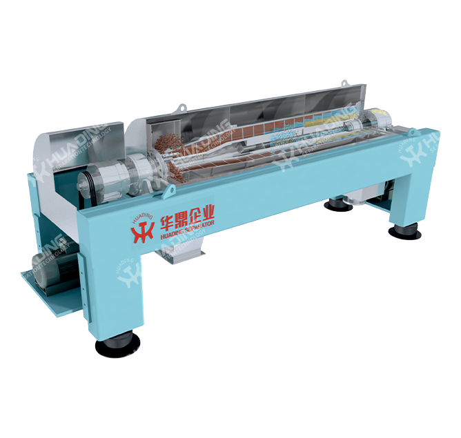
A common misunderstanding is that a horizontal decanter centrifuge bowl is a fixed, generic shape that simply gets scaled up or down. In practice, the cylindrical-to-conical ratio, the beach angle of the conical section, and the number of screw flights are all selected according to the material the machine will process. A sludge dewatering application with fine, compressible solids calls for a longer conical beach angle to give the cake more time to drain before discharge. A mineral processing application with coarse, abrasive particles instead prioritizes a shorter, more robust conical section paired with heavier wear protection. This is why two decanter centrifuges with the same bowl diameter can look almost identical from the outside while behaving very differently once running, because the internal geometry has been engineered around the target slurry.
The differential speed mechanism deserves the same attention. This is generated by a planetary gearbox mounted on the bowl shaft, and the gear ratio selected during manufacturing sets the achievable differential speed range for that specific machine. A narrow differential range is suitable for free-draining materials that clarify quickly, while a wider adjustable range is specified when the factory line will process a mix of feed materials with different settling characteristics. Getting this ratio wrong at the design stage cannot easily be corrected later, which is why differential speed range is one of the first parameters clarified during the technical discussion before a decanter centrifuge order is confirmed.
Typical Bowl Size Series and Process Reference Parameters
| Bowl Diameter | 220 mm | 350 mm | 500 mm | 650 mm |
| Length to Diameter Ratio | 3.0 : 1 | 3.2 : 1 | 3.5 : 1 | 4.0 : 1 |
| Maximum Bowl Speed | 6000 rpm | 4500 rpm | 3600 rpm | 2800 rpm |
| Typical Feed Capacity | 1–3 m³/h | 4–10 m³/h | 10–25 m³/h | 25–50 m³/h |
| Main Motor Power | 5.5–7.5 kW | 15–22 kW | 30–45 kW | 55–75 kW |
| Typical Application | Laboratory / pilot trial | Small process line | Municipal sludge line | Large industrial process |
Values above are general reference ranges; actual selection depends on solids content, particle size distribution and required cake dryness for each project.
Whether a machine is built as a 2 phase decanter centrifuge separator or a three-phase configuration is decided before manufacturing begins, because the two designs are not interchangeable through simple adjustment. A two-phase build separates solids from a single liquid phase and is the configuration most often specified for sludge dewatering, starch washing, and juice clarification. A three-phase build adds a second, independently adjustable liquid outlet so that a light liquid phase, such as oil, can be separated from a heavy liquid phase, such as water, at the same time as the solids are removed. This is the configuration commonly manufactured for oil-water-solid separation duties. The three-phase version requires an additional centripetal pump inside the bowl and a more complex outlet weir arrangement, which is why it is priced and lead-timed differently from a standard 2 phase decanter centrifuge separator during production planning.
Point Worth Noting During Specification
A machine ordered as two-phase cannot later be field-converted to three-phase, because the bowl casting, the internal weir plates, and the gearbox torque rating are all matched to the original configuration during manufacturing. Confirming the phase requirement early avoids costly re-ordering.
Municipal and Industrial Wastewater
Continuous sludge dewatering lines running around the clock, where mechanical reliability and low polymer consumption directly affect operating cost.
Chemical and Pharmaceutical Processing
Crystallization and catalyst recovery duties that require corrosion-resistant wetted parts and tight control over shear sensitivity.
Food and Starch Production
Hygienic-grade bowls with polished internal surfaces for starch washing, protein recovery, and fruit and vegetable juice clarification.
Oil Field and Drilling Fluid Recovery
Heavy-duty three-phase builds designed to withstand abrasive drilling mud and separate oil, water and solids in a single continuous pass.
Mining and Mineral Processing
Reinforced conical sections and tungsten carbide wear protection for tailings dewatering and mineral concentrate recovery.
Marine and Bilge Water Treatment
Compact, vibration-tolerant builds engineered to operate reliably in a shipboard environment with limited installation footprint.
Before any decanter centrifuge is released for shipment, the assembled rotating unit is run on a no-load test bench to record vibration amplitude at incremental speed steps up to the rated maximum. This step catches balance issues that would otherwise only appear after months of field operation. Following the no-load test, a wet run using a reference slurry is carried out wherever the customer's process allows it, so that separation performance, torque draw under load, and bearing temperature rise can all be verified against the design specification. Surface finish of the wetted parts is checked against the specified roughness value, since a rougher-than-specified internal surface increases the risk of solids adhesion and reduces effective throughput over time. Only after these checks are recorded does the unit proceed to painting, packing, and dispatch.
Checks Typically Recorded at Final Inspection
Customers approaching a manufacturer with an existing separation problem usually bring one of two starting points: either a sample of the material to be processed, or a target specification such as required cake dryness and clarified liquid quality. Laboratory-scale trials using a small pilot decanter centrifuge are the most reliable way to translate either starting point into a production-scale recommendation, because slurry behavior at bench scale using a beaker centrifuge does not reliably predict continuous performance at production flow rates. During a pilot trial, feed concentration, differential speed, and pond depth inside the bowl are adjusted systematically while cake dryness and centrate clarity are measured, and the resulting data set becomes the basis for sizing the production machine rather than relying on catalog figures alone.
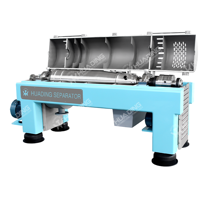
Maintenance access is also considered at the design stage rather than treated as an afterthought. Machines destined for continuous three-shift operation are typically specified with a swing-out casing or removable top cover so that the screw assembly can be inspected without a full crane lift, while machines destined for intermittent or seasonal operation may be built to a simpler, lower-cost access configuration. This distinction affects how the frame, casing hinges, and lifting points are manufactured, and is one more reason why describing the intended duty cycle at the inquiry stage leads to a better-matched machine.
Two-Phase vs Three-Phase Build Comparison
| Separated Phases | Solid / single liquid | Solid / light liquid / heavy liquid |
| Internal Pump | Not required | Centripetal pump fitted |
| Outlet Weir Design | Single adjustable weir | Dual independently adjustable weirs |
| Typical Duty | Sludge, starch, juice | Drilling fluid, oily wastewater, tank bottom sludge |
| Relative Mechanical Complexity | Standard | Higher |
Is a decanter centrifuge the same thing as any centrifuge on the market?
No. Centrifuge is the broad category, while a decanter centrifuge refers specifically to the horizontal, continuous-feed, screw-discharge design described throughout this page. Disc-stack and basket-type machines fall under the same broad category but are built and operated differently.
Does decant mean the same process as centrifuge separation?
Decant refers to gravity settling followed by pouring off the clear liquid, a slow batch process. A decanter centrifuge instead uses continuous mechanical force to achieve the same solid-liquid split within seconds rather than hours, which is the main reason it replaced manual decanting in most continuous production lines.
What determines how efficient a specific unit will be on a given material?
Efficiency is not a fixed number stamped on the machine; it results from matching bowl speed, differential speed, pond depth, and feed rate to the actual particle size and density of the material. A correctly matched unit consistently achieves high solids recovery, while an undersized or mismatched unit on the same material will underperform regardless of nameplate rating.
How is a maintenance schedule usually structured for continuous operation?
Daily checks cover bearing temperature and unusual noise, weekly checks cover lubrication levels, monthly checks cover wear-part condition on the screw flights, and an annual teardown inspection covers dynamic balance and gearbox internal wear. Following this cadence is what allows a well-built decanter centrifuge to reach its full design service life.
Selecting a supplier for a decanter centrifuge ultimately comes down to how much of the process above is visible and verifiable rather than taken on trust. Requesting material certificates, balance test records, and pilot trial data before finalizing an order gives a much clearer picture of long-term reliability than comparing nameplate capacity figures alone.
Copyright ©Yixing Huading Machinery Co.,Ltd. All Rights Reserved. Custom Centrifugal Separator Factory