
 English
 русский
 Español
 عربى
عربى 中文简体
中文简体


 centrifuge")
 Contact Us

Application
View More
Centrifugal separation is a common process in the energy industry. Decanter centrifuges and disc separators are often presented individually or in combination in various process units. For example, in comprehensive use of oil sludge from oil fields, treatment of drilling fluids from oil and gas fields, treatment and comprehensive use of various waste oils and fluids, treatment of coal tar, production of biodiesel and other process units in various application scenarios, decanters and disc separators play a huge role as core process equipment.
If you are involved in the energy industry, it is important to understand how decanter centrifuges and separators work. This knowledge will help you to choose the right type of equipment for your needs and to find the suitable equipment for you.

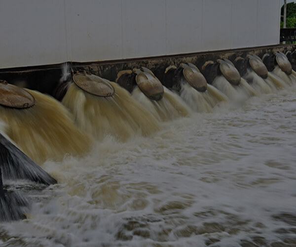
Introduction to Oily Wastewater Challenges In the global industrial landscape, the management of waste water containing oil has become an unavoidable challenge for sectors ranging from petrochemicals and metalworking to food processing and marine transport. Oily wastewater typically contains free oil, emulsified oil, dissolved oil, and suspended solids. If discharged directly into the environment, these pollutants form an impermeable film on water surfaces, preventing oxygen exchange and devastating aquatic ecosystems. Furthermore, strict environmental regulations now impose heavy fines for non-compliance, making efficient treatment not just a moral obligation but a financial necessity for modern enterprises. Traditional methods like gravity separation, air flotation, or chemical coagulation often struggle to handle complex emulsions or high solid loads. These methods are frequently plagued by high maintenance costs, excessive chemical usage, and the inability to recover high-purity oil. Huading Separator addresses these pain points with advanced Centrifugal force technology, providing a robust solution that turns environmental liabilities into valuable resource recovery opportunities. The Huading 3-phase decanter Solution Our flagship solution for this application is the 3-phase decanter centrifuge. Unlike 2-phase separators that only separate solids from liquids, the 3-phase system simultaneously isolates two immiscible liquid phases (oil and water) and one solid phase in a single, continuous process. This "one-step" efficiency is what sets Huading technology apart in the competitive separation market. Key Working Principles: Feeding:The contaminated mixture is fed through a stationary inlet pipe into the accelerating distributor of the bowl. Acceleration:Under the influence of high Centrifugal force, the components are stratified based on their density. The heavy solids settle against the bowl wall, the heavy liquid (water) forms an outer ring, and the light liquid (oil) forms an inner ring. Separation & Discharge:The Screw conveyor continuously pushes the solids toward the conical end for discharge. Simultaneously, the clarified water and purified oil are discharged at the cylindrical end through separate adjustable outlets. Advanced Technical Features and Benefits Huading’s engineering team has optimized every component of the centrifuge to ensure maximum reliability and performance in harsh industrial environments. Our use of Duplex stainless steel for critical parts ensures resistance against the corrosive nature of saline or acidic wastewaters. To combat the abrasive nature of suspended solids like sand or metal fines, we apply a thick layer of Tungsten carbide tiles to the screw conveyor flights, significantly extending the service life of the machine. Another breakthrough is our Mechanical thickening capability. By precisely controlling the bowl speed and differential speed via our dual VFD system, we can achieve high-density sludge discharge, reducing the volume of hazardous waste by up to 90%. This drastic reduction in sludge volume directly translates into lower transportation and disposal costs for the operator. Economic Value and Environmental Compliance The primary driver for implementing a Huading Decanter centrifuge is the rapid Return on Investment (ROI). By recovering high-purity oil (often exceeding 98% purity), companies can sell this oil back into the market or reuse it as fuel, effectively paying for the equipment through resource recovery. Moreover, the clarified water phase can often be reused for cooling or cleaning within the factory, promoting a "Closed-loop" water management system that aligns with "Zero Liquid Discharge" (ZLD) goals. Performance Metric Huading Standard Oil Removal Rate 99.5% - 99.9% Solids Dewatering Up to 35% Dryness Operation Mode 24/7 Continuous Operation Automation PLC with Remote Monitoring
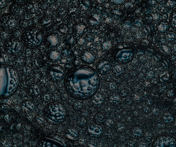
Navigating the Complexity of Oil Sludge Mixtures In the upstream and downstream petroleum industry, one of the most difficult materials to manage is the oil/water/solids mixtures, commonly referred to as oil sludge. Found in oil tank bottoms, lagoon residues, and refinery slop oil, these mixtures are characterized by high viscosity, varying chemical compositions, and heavy solid loading. Unlike standard wastewater, oil sludge acts as a stable emulsion that resists gravity settling and traditional filtration. Without proper treatment, these mixtures represent a significant environmental liability and a waste of valuable hydrocarbons trapped within the matrix. The core challenge lies in breaking the emulsion and effectively separating the fine silt, sand, and organic solids from the liquid phases. Huading Separator has engineered a specialized Decanter centrifuge platform specifically for these high-torque, heavy-duty applications, ensuring that even the most stubborn sludge can be profitably processed. The 3-Phase Decanter: Engineering for Extreme Conditions The Huading 3-phase decanter is the heart of the sludge treatment process. Designed for high Centrifugal force, the machine forces the immediate separation of the high-density solids from the liquid layers. Because oil sludge often contains abrasive particles, we utilize advanced wear-protection technologies. The discharge ports are fitted with replaceable ceramic bushings, and the Screw conveyor is reinforced with sintered Tungsten carbide to withstand the scouring action of sand and grit. The Separation Advantage: Hydrocarbon Recovery:Reclaim up to 95% of the oil trapped in the sludge for refining or sale. Water Purification:Produce effluent water suitable for injection or further biological treatment. Solid Disposal:Create a dry, stackable cake that minimizes landfill costs and facilitates incineration. Innovative Control with Dual Drive VFD Success in processing oil/water/solids mixtures depends on the ability to adapt to changing feed conditions. Huading’s dual VFD (Variable Frequency Drive) system allows the operator to adjust the bowl speed and the differential speed of the conveyor independently and in real-time. This means if the solids content suddenly increases, the system can automatically increase the differential speed to prevent clogging, ensuring Continuous operation without manual intervention. Furthermore, our PLC-based control system monitors the torque on the scroll. If the torque reaches a critical threshold, the feed is automatically throttled or stopped to protect the internal gear units, ensuring the long-term mechanical integrity of the centrifuge. Mobile Solutions for Field Remediation Many oil sludge projects are located at remote oilfields or temporary cleanup sites. Huading offers Mobile Solutions where the entire separation plant—including the centrifuge, feed pumps, polymer dosing system, and control room—is integrated into a standard ISO container. This "plug-and-play" approach allows for rapid deployment and minimal onsite construction, significantly reducing the project's capital footprint. Feature Advantage High Torque Gearbox Handles high solid loading without stalling Plow-Type Conveyor Improves solids transport and clarity Adjustable Impeller Allows fine-tuning of the oil/water interface during operation Vibration Isolation Reduces structural stress and noise Environmental Impact and Sustainable Operations By implementing Huading’s centrifugal separation, refineries and oilfield operators transition from a "waste disposal" mindset to a "resource recovery" model. Recovering oil from sludge directly reduces the carbon footprint of the facility by decreasing the need for virgin crude production and minimizing the energy required for waste transport. Huading is committed to providing the technology that makes industrial sustainability a profitable reality.
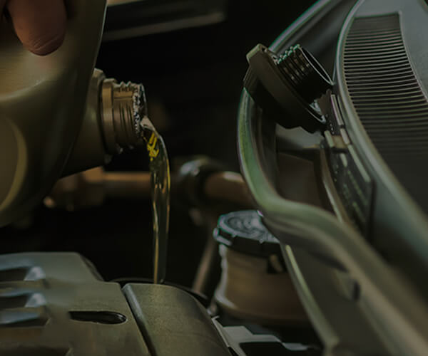
The Vital Importance of Lubricant Cleanliness In high-stakes industrial environments—such as power generation turbines, marine propulsion engines, and heavy manufacturing presses—the Processing and handling of lube oils is the single most important factor in determining the lifespan of rotating equipment. Lubricating oil serves as the "blood" of the machine, reducing friction, carrying away heat, and preventing corrosion. However, during operation, lube oil is constantly bombarded by contaminants: moisture from condensation, metallic wear particles, and carbon soot. These contaminants accelerate oil oxidation and can lead to catastrophic bearing failure if left unchecked. Traditional paper or cartridge filters, while common, have significant limitations. They cannot remove water and quickly become clogged by fine debris, leading to pressure drops and frequent, expensive filter replacements. Huading Separator offers a superior alternative: the high-speed Disc Stack Centrifuge. Superior Purification with Disc Stack Technology The Disc stack centrifuge utilizes extreme Centrifugal force (up to 12,000G) to remove even the smallest sub-micron particles and free water from the oil. Unlike filters, which act only on size, the centrifuge separates based on density differences. This allows for the simultaneous removal of heavy solid particles and the separation of water from the oil phase in a single pass. Why Choose Centrifugal Purification? Continuous Online Operation:The centrifuge can be piped directly into the oil reservoir, providing constant cleaning without ever stopping the main engine or turbine. No Consumables:Since separation is purely mechanical, there are no filter elements to buy, stock, or dispose of as hazardous waste. Water Removal:Effectively removes 99.9% of free water, which is impossible for standard mechanical filters. Advanced Engineering: The Centripetal Pump A key feature of Huading's lube oil purifiers is the integrated Centripetal pump. This device converts the kinetic energy of the rotating liquid into pressure, allowing the purified oil to be discharged at a steady pressure without the need for an external discharge pump. This simplifies the system design and reduces the potential for leaks. Furthermore, our "Hydrohermetic" feed system ensures that the oil enters the bowl gently, preventing the shearing of delicate chemical additives that are essential for high-performance lubrication. For marine and offshore applications, our systems are built with Duplex stainless steel to resist salt-air corrosion and are designed to operate reliably even under significant pitch and roll conditions. The automated sludge discharge system ensures that separated solids are ejected without interrupting the purification process, enabling truly unattended operation. Economic and Environmental Benefits The economic argument for Huading lube oil purifiers is compelling. By maintaining oil at peak cleanliness, the interval between oil changes can be extended by 2x or even 3x, drastically reducing oil procurement costs. More importantly, the reduction in wear on critical components like bearings and gears translates into fewer unplanned outages and longer overall machine life. Environmentally, the reduction in waste oil volume supports corporate "Green" initiatives and reduces the risk of environmental contamination. Parameter Typical Performance Solid Removal Efficiency 99% down to 1 micron Water Content After Treatment < 100 ppm Flow Capacity 500 to 20,000 Liters/Hour Maintenance Interval Up to 8,000 Hours
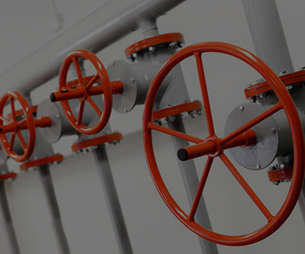
/* === SECTION SCOPE: all styles prefixed to avoid global conflicts === */ .fuel-app-section { font-family: 'Georgia', 'Times New Roman', serif; color: #1a1a1a; background: #f5f5f5; margin: 0 auto; } /* --- Hero Banner --- */ .fuel-app-section .fap-hero { background: linear-gradient(135deg, #1a0002 0%, #c70f18 55%, #8b0000 100%); border-radius: 4px; padding: 56px 60px; margin-bottom: 60px; position: relative; overflow: hidden; } .fuel-app-section .fap-hero::before { content: ''; position: absolute; right: -60px; top: -60px; width: 340px; height: 340px; border-radius: 50%; border: 40px solid rgba(255,255,255,0.05); } .fuel-app-section .fap-hero::after { content: ''; position: absolute; right: 60px; bottom: -80px; width: 220px; height: 220px; border-radius: 50%; border: 30px solid rgba(255,255,255,0.04); } .fuel-app-section .fap-hero-label { font-size: 12px; letter-spacing: 3px; text-transform: uppercase; color: rgba(255,255,255,0.6); margin-bottom: 16px; font-family: 'Arial Narrow', Arial, sans-serif; } .fuel-app-section .fap-hero-title { font-size: 36px; line-height: 1.25; color: #fff; font-weight: 700; margin: 0 0 20px 0; max-width: 680px; position: relative; z-index: 1; } .fuel-app-section .fap-hero-title em { color: #ffb3b8; font-style: normal; } .fuel-app-section .fap-hero-desc { font-size: 16px; line-height: 30px; color: rgba(255,255,255,0.85); max-width: 620px; margin: 0; position: relative; z-index: 1; } .fuel-app-section .fap-hero-stats { display: flex; gap: 40px; margin-top: 36px; position: relative; z-index: 1; flex-wrap: wrap; } .fuel-app-section .fap-stat { border-left: 3px solid rgba(255,255,255,0.4); padding-left: 16px; } .fuel-app-section .fap-stat-num { font-size: 28px; font-weight: 700; color: #fff; line-height: 1.1; display: block; } .fuel-app-section .fap-stat-label { font-size: 12px; color: rgba(255,255,255,0.65); letter-spacing: 1px; text-transform: uppercase; } /* --- Section Heading System --- */ .fuel-app-section .fap-section-tag { font-size: 12px; letter-spacing: 3px; text-transform: uppercase; color: #c70f18; font-family: 'Arial Narrow', Arial, sans-serif; margin-bottom: 10px; display: block; } .fuel-app-section .fap-h2 { font-size: 28px; line-height: 1.3; font-weight: 700; color: #111; margin: 0 0 20px 0; border-left: 5px solid #c70f18; padding-left: 18px; } .fuel-app-section .fap-h3 { font-size: 20px; line-height: 1.5; font-weight: 700; color: #1a1a1a; margin: 0 0 12px 0; } .fuel-app-section .fap-body { font-size: 16px; line-height: 30px; color: #333; margin-bottom: 16px; } .fuel-app-section .fap-body-sm { font-size: 14px; line-height: 2; color: #444; } /* --- Divider --- */ .fuel-app-section .fap-divider { height: 1px; background: #e8e8e8; margin: 50px 0; position: relative; } .fuel-app-section .fap-divider::after { content: ''; position: absolute; left: 0; top: 0; width: 80px; height: 3px; background: #c70f18; top: -1px; } /* --- Two-column Layout --- */ .fuel-app-section .fap-two-col { display: grid; grid-template-columns: 1fr 1fr; gap: 48px; align-items: start; } .fuel-app-section .fap-three-col { display: grid; grid-template-columns: repeat(3, 1fr); gap: 28px; } /* --- Process Flow --- */ .fuel-app-section .fap-flow { display: flex; flex-direction: column; gap: 0; margin: 30px 0; } .fuel-app-section .fap-flow-item { display: flex; align-items: flex-start; gap: 24px; padding: 24px 28px; border-left: 3px solid #e8e8e8; position: relative; } .fuel-app-section .fap-flow-item.active { border-left-color: #c70f18; background: #fff5f5; } .fuel-app-section .fap-flow-num { width: 40px; height: 40px; min-width: 40px; border-radius: 50%; background: #c70f18; color: #fff; font-size: 16px; font-weight: 700; display: flex; align-items: center; justify-content: center; margin-left: -22px; } .fuel-app-section .fap-flow-item:not(.active) .fap-flow-num { background: #888; } .fuel-app-section .fap-flow-content {} .fuel-app-section .fap-flow-title { font-size: 16px; line-height: 30px; font-weight: 700; color: #111; margin-bottom: 4px; } /* --- Highlight Cards --- */ .fuel-app-section .fap-card { background: #f9f9f9; border: 1px solid #ebebeb; border-top: 4px solid #c70f18; padding: 28px 24px; border-radius: 0 0 4px 4px; } .fuel-app-section .fap-card-accent { background: #c70f18; color: #fff; padding: 28px 24px; border-radius: 4px; } .fuel-app-section .fap-card-accent .fap-h3 { color: #fff; } .fuel-app-section .fap-card-accent .fap-body-sm { color: rgba(255,255,255,0.85); } /* --- Table --- */ .fuel-app-section .fap-table-wrap { overflow-x: auto; margin: 28px 0; } .fuel-app-section .fap-table { width: 100%; border-collapse: collapse; font-size: 14px; line-height: 2; } .fuel-app-section .fap-table tr:first-child td { background: #c70f18; color: #fff; font-weight: 700; font-size: 14px; line-height: 2; padding: 14px 18px; white-space: nowrap; } .fuel-app-section .fap-table td { padding: 12px 18px; border-bottom: 1px solid #ebebeb; color: #333; vertical-align: top; } .fuel-app-section .fap-table tr:not(:first-child):nth-child(even) td { background: #fafafa; } .fuel-app-section .fap-table tr:not(:first-child):hover td { background: #fff5f5; } .fuel-app-section .fap-table td:first-child { font-weight: 600; color: #111; border-left: 3px solid #c70f18; } /* --- Highlight Box --- */ .fuel-app-section .fap-highlight { background: #fff5f5; border-left: 5px solid #c70f18; padding: 24px 28px; margin: 28px 0; border-radius: 0 4px 4px 0; } .fuel-app-section .fap-highlight p { font-size: 16px; line-height: 30px; color: #222; margin: 0; } .fuel-app-section .fap-highlight strong { color: #c70f18; } /* --- Application Scenario Cards --- */ .fuel-app-section .fap-scenario-grid { display: grid; grid-template-columns: repeat(2, 1fr); gap: 20px; margin: 28px 0; } .fuel-app-section .fap-scenario-card { background: #fff; border: 1px solid #e0e0e0; padding: 24px 22px; position: relative; overflow: hidden; } .fuel-app-section .fap-scenario-card::before { content: ''; position: absolute; top: 0; left: 0; right: 0; height: 3px; background: #c70f18; } .fuel-app-section .fap-scenario-label { font-size: 11px; letter-spacing: 2px; text-transform: uppercase; color: #c70f18; font-family: Arial, sans-serif; margin-bottom: 8px; display: block; } .fuel-app-section .fap-scenario-title { font-size: 18px; line-height: 1.8; font-weight: 700; color: #111; margin-bottom: 10px; } /* --- Spec Badge Row --- */ .fuel-app-section .fap-badges { display: flex; flex-wrap: wrap; gap: 12px; margin: 20px 0; } .fuel-app-section .fap-badge { background: #1a0002; color: #fff; font-size: 14px; line-height: 2; padding: 2px 16px; border-radius: 2px; font-family: 'Arial Narrow', Arial, sans-serif; letter-spacing: 0.5px; } .fuel-app-section .fap-badge-outline { background: transparent; color: #c70f18; border: 1px solid #c70f18; font-size: 14px; line-height: 2; padding: 2px 16px; border-radius: 2px; } /* --- CTA Strip --- */ .fuel-app-section .fap-cta { background: linear-gradient(135deg, #111 0%, #2a0004 100%); padding: 40px 50px; display: flex; align-items: center; justify-content: space-between; gap: 30px; margin-top: 60px; border-radius: 4px; flex-wrap: wrap; } .fuel-app-section .fap-cta-text { font-size: 22px; color: #fff; font-weight: 700; line-height: 1.4; max-width: 560px; } .fuel-app-section .fap-cta-text span { color: #ff6a72; } .fuel-app-section .fap-btn { display: inline-block; background: #c70f18; color: #fff; font-size: 14px; line-height: 2; padding: 10px 32px; text-decoration: none; font-weight: 700; letter-spacing: 1px; text-transform: uppercase; border: none; cursor: pointer; transition: background 0.2s; white-space: nowrap; font-family: Arial, sans-serif; } .fuel-app-section .fap-btn:hover { background: #a00d14; } /* --- FAQ Accordion --- */ .fuel-app-section .fap-faq-item { border-bottom: 1px solid #e8e8e8; } .fuel-app-section .fap-faq-q { font-size: 16px; line-height: 30px; font-weight: 700; color: #111; padding: 18px 0; cursor: pointer; display: flex; justify-content: space-between; align-items: center; gap: 16px; } .fuel-app-section .fap-faq-q:hover { color: #c70f18; } .fuel-app-section .fap-faq-toggle { width: 24px; height: 24px; min-width: 24px; border: 2px solid #c70f18; color: #c70f18; display: flex; align-items: center; justify-content: center; font-size: 18px; font-weight: 400; border-radius: 50%; transition: transform 0.2s; font-family: Arial, sans-serif; } .fuel-app-section .fap-faq-item.open .fap-faq-toggle { transform: rotate(45deg); } .fuel-app-section .fap-faq-a { font-size: 14px; line-height: 2; color: #444; padding: 0 0 18px 0; display: none; } .fuel-app-section .fap-faq-item.open .fap-faq-a { display: block; } /* --- Responsive --- */ @media (max-width: 768px) { .fuel-app-section { padding: 40px 20px; } .fuel-app-section .fap-hero { padding: 36px 28px; } .fuel-app-section .fap-hero-title { font-size: 26px; } .fuel-app-section .fap-two-col, .fuel-app-section .fap-three-col, .fuel-app-section .fap-scenario-grid { grid-template-columns: 1fr; } .fuel-app-section .fap-cta { padding: 30px 24px; } .fuel-app-section .fap-hero-stats { gap: 24px; } } Energy Industry Application Industrial Centrifuge for Fuel Purification in Diesel Engines & Gas Turbines Disc stack centrifuge and decanter centrifuge engineered for continuous processing and handling of fuels — removing water, particulates, and sludge to protect diesel engines and gas turbines from contamination-related failures. >99% Water Separation Efficiency 5,000–15,000 rpm Operational Speed Range 2–20 µm Particle Removal Capacity 24/7 Continuous Operation Core Challenge Why Fuel Cleanliness Is Critical for Diesel Engines and Gas Turbines Diesel engines and gas turbines are precision mechanical systems that demand exceptionally clean fuel to maintain operational reliability and combustion efficiency. In practice, fuels sourced from refineries, storage tanks, or marine bunkers invariably contain free water, emulsified water, biological contaminants, rust particles, sand, and catalytic fines — all of which are capable of causing irreversible damage to injectors, fuel pumps, combustion chambers, and turbine blades. Free water accelerates microbial growth in fuel storage systems, producing acidic by-products that corrode metal surfaces. Solid particulates, even those measured at 5–20 µm, cause abrasive wear on precision-engineered components toleranced to sub-micron levels. Catalytic fines (cat fines) originating from residual fuel blending are among the most destructive — their hardness (7–9 on the Mohs scale) far exceeds that of most alloy steels used in engine construction. A properly selected and operated industrial centrifuge addresses all of these contamination types simultaneously, through continuous centrifugal separation rather than passive filtration. Unlike filter elements that become saturated and require frequent replacement, the centrifugal process is self-sustaining, cost-effective, and capable of handling high-viscosity heavy fuels such as HFO (Heavy Fuel Oil) and IFO-380. ISO 8217 defines the maximum contaminant limits for marine and power generation fuels. Compliance with these limits relies almost entirely on effective centrifugal purification prior to fuel injection — filtration alone cannot achieve the required water and sediment removal at the throughput rates demanded by large-capacity diesel engines and gas turbines. Primary Contaminants Removed Contaminant Type Source Risk to Equipment Free Water Condensation, tank ingress Corrosion, microbial growth Emulsified Water Fuel blending, turbulent flow Injector erosion, misfiring Catalytic Fines Residual fuel blending Severe abrasive wear Rust & Sediment Tank corrosion, pipeline scale Nozzle blockage, filter damage Biological Growth Water-contaminated storage Fuel degradation, filter blocking Sludge & Asphaltenes Fuel ageing, blending incompatibility Combustion instability Working Principle How the Industrial Centrifuge Processes and Purifies Fuel The disc stack centrifuge (disc separator) is the preferred machine type for fuel purification in diesel and gas turbine applications. Its operating principle leverages centrifugal acceleration — typically 5,000–10,000 × g — to achieve phase separation that would take hours in gravity settling equipment in a matter of seconds. 01 Preheating Incoming fuel is preheated (typically to 95–98°C for HFO, 40–60°C for diesel) to reduce viscosity, enabling effective separation. Correct temperature is essential — insufficient heating prevents water from coalescing; overheating may cause flash evaporation. 02 Centrifugal Bowl Separation Preheated fuel enters the rotating bowl assembly containing stacked conical disc inserts. Centrifugal force stratifies the mixture: dense water and solids migrate outward to the bowl wall; clean fuel remains in the inner zone and exits continuously through the light-phase outlet. 03 Purifier vs. Clarifier Mode Operating in purifier mode, the centrifuge separates both water and solids from fuel (three-phase separation). In clarifier mode, it operates as a two-phase separator for solids removal when the fuel is essentially dry. Most marine and power generation fuel treatment systems operate both a purifier and a clarifier in series. 04 Sludge Ejection (Self-Cleaning) Accumulated solids and water sludge are discharged automatically at timed intervals via the self-cleaning (desludging) mechanism. This allows true continuous operation without manual intervention, critical for 24/7 power plant and marine propulsion applications. 05 Clean Fuel to Day Tank / Injection System Purified fuel meeting the required NAS, ISO 4406, or CIMAC cleanliness specifications exits to the day tank or directly to the high-pressure fuel injection system of the diesel engine or gas turbine. Equipment Selection Centrifuge Type Selection for Different Fuel Handling Requirements Different fuel types and system configurations demand different centrifuge specifications. The following comparison provides the technical basis for selecting the correct machine configuration. Parameter Disc Stack Centrifuge (Purifier Mode) Disc Stack Centrifuge (Clarifier Mode) Decanter Centrifuge Separation Type Liquid-liquid-solid (three-phase) Liquid-solid (two-phase) Solid-liquid (high solids content) Applicable Fuel HFO, IFO-380, MDO, Bunker fuel MGO, Marine Diesel, Gas Turbine Fuel Fuel sludge & slop oil recovery Centrifugal Force 5,000–10,000 × g 5,000–10,000 × g 2,000–4,000 × g Water Removal Yes (continuous) Limited (dry fuel only) Yes (high water content) Solids Handling Moderate (auto-discharge) High (auto-discharge) Very high (continuous scroll) Operation Mode Continuous / self-cleaning Continuous / self-cleaning Continuous Typical Flow Rate 0.5–25 m³/h 0.5–30 m³/h 1–50 m³/h Primary Application Main fuel purification Secondary polishing Sludge dewatering For heavy fuel oil (HFO) treatment on large marine diesel engines and gas turbines, CIMAC Guidelines recommend installing a disc stack centrifuge purifier and clarifier in series, with combined flow capacity calculated at 4–8× the engine fuel consumption rate to allow adequate residence time and separation efficiency. Application Scenarios Specific Applications Across Diesel and Gas Turbine Systems Power Generation Stationary Diesel Generator Sets Large-capacity diesel gensets used in power plants, data centers, and industrial facilities operate on MDO or HFO and require continuous fuel treatment. The disc stack centrifuge is installed in the fuel treatment module upstream of the day tank, operating at 40–98°C depending on fuel grade. Removal of cat fines to below 15 mg/kg (per ISO 8217 limit) is achieved through correctly sized centrifugal purification. MDO / HFO 0.5–15 m³/h Cat Fine Removal Marine Application Marine Main Engine & Auxiliary Fuel Treatment Onboard marine fuel treatment is a mandatory process for vessels burning HFO or VLSFO. The centrifuge system must handle bunker fuel with varying viscosity (180–700 cSt at 50°C) and contamination levels. A duplex centrifuge arrangement (duty/standby) ensures uninterrupted fuel supply. Automated self-cleaning cycles are timed based on sludge accumulation rate, which varies with fuel quality. HFO / VLSFO Duplex Arrangement IMO Compliant Gas Turbine Industrial Gas Turbine Liquid Fuel Treatment Gas turbines burning liquid fuel (crude oil, naphtha, distillate, or diesel) require fuel cleanliness at ISO 4406 Class 16/13 or better. Trace sodium and vanadium compounds — which form corrosive deposits on hot-section turbine blades at temperatures above 650°C — must be removed by water-washing in combination with centrifugal separation. The centrifuge achieves Na+K levels below 0.5 ppm and vanadium below 0.5 ppm through fuel washing and separation. ISO 4406 Class 16/13 Na+K < 0.5 ppm Hot Corrosion Prevention Fuel Storage Shore-Based Fuel Storage Tank Treatment Fuel storage tanks accumulate water and sludge at the bottom over time, regardless of incoming fuel quality. A centrifuge polishing circuit recirculates stored fuel through the separator to maintain tank cleanliness, prevent biological contamination, and extend fuel service life. This is especially important for emergency generator fuel reserves where storage periods may extend 6–24 months. Tank Recirculation Long-term Storage Microbial Control Technical Specifications Key Technical Parameters for Fuel Centrifuge Selection Selecting the correct centrifuge for fuel purification requires matching machine capacity to the fuel consumption rate of the connected engine or turbine, accounting for fuel viscosity and density, and setting operational parameters (bowl speed, temperature, flow rate) correctly. Undersized equipment is the most common cause of inadequate fuel cleanliness in the field. Specification Value / Range Bowl Speed 5,000 – 15,000 rpm Centrifugal Factor (Z) 4,500 – 12,000 × g Flow Capacity 0.5 – 30 m³/h Operating Temperature 40°C – 98°C Fuel Viscosity Range 1.5 – 700 cSt at 50°C Particle Separation ≥ 2 µm effective Water Outlet Concentration < 0.1% (v/v) in clean fuel Sludge Discharge Automatic (self-cleaning bowl) Materials (product contact) SUS316L, Duplex SS, Titanium (optional) Mechanical Seal Cartridge type, carbon/SiC faces Sizing Guidelines Centrifuge throughput capacity should be sized to provide sufficient dwell time for effective separation. The general formula used in marine and power generation engineering: Qcentrifuge = Qengine × Safety Factor (4–8×) Where Qengine is the maximum fuel consumption at full load. The 4–8× safety factor accounts for temperature-dependent viscosity variation, varying contamination levels, and sludge accumulation at bowl wall which progressively reduces effective separation volume. Standard Compliance Our industrial centrifuges for fuel purification are designed and tested to comply with the following standards: ISO 8217 CIMAC W17 ISO 4406 NAS 1638 API 614 ATEX Process Engineering Critical Process Variables in Fuel Centrifugal Purification Temperature Control Fuel viscosity decreases with increasing temperature, directly improving separation efficiency. For HFO with viscosity above 380 cSt at 50°C, the centrifuge inlet temperature must reach 95–98°C to bring viscosity to below 20 cSt — the threshold for effective disc stack separation. Precise temperature control (±2°C) prevents both inadequate separation at low temperatures and flash evaporation or fuel degradation at excessive temperatures. Flow Rate Optimization Throughput directly affects separation efficiency — at higher flow rates, the residence time of fuel within the disc stack decreases, reducing the opportunity for water droplets and particles to migrate to the bowl wall. Operating the centrifuge at 70–85% of its rated capacity provides the optimal balance between throughput and separation efficiency. Overspeeding the centrifuge with excessive flow is a common operator error that compromises fuel cleanliness. Gravity Disc Selection In purifier mode, the gravity disc (or dam ring) establishes the water-fuel interface within the rotating bowl. Selecting the correct gravity disc diameter for the specific fuel density (typically 850–1010 kg/m³ at 15°C) is essential. Using an incorrect disc shifts the interface position — if the interface moves too far inward, water bypasses the bowl and exits with the clean fuel; too far outward, clean fuel is discharged with the water sludge. Technical Q&A Frequently Asked Questions About Fuel Centrifuge Systems What is the difference between a fuel purifier and a fuel clarifier centrifuge? + A purifier is configured for three-phase separation, simultaneously removing free water and solid particles from fuel containing significant water content. It uses a gravity disc to maintain a water-fuel interface inside the bowl. A clarifier operates as a two-phase separator (no interface disc), designed specifically for solids removal from fuel that is already largely dry. In a standard marine fuel treatment system, fuel passes through the purifier first (water + solids removal), then through the clarifier (polishing, solids only) to achieve the highest cleanliness level before entering the service tank. Can a disc stack centrifuge handle both diesel fuel and heavy fuel oil (HFO)? + Yes, but the operating parameters must be adjusted for each fuel type. HFO (density 950–1010 kg/m³ at 15°C, viscosity 180–700 cSt at 50°C) requires higher operating temperatures (95–98°C), a heavier gravity disc, and lower flow rates relative to the machine's nominal capacity. Marine diesel oil (density 840–890 kg/m³, viscosity 2–14 cSt at 40°C) operates at lower temperatures (40–60°C) with a lighter gravity disc. When switching between fuel types, the gravity disc must be changed and operating temperature recalibrated accordingly. What causes centrifuge overflow (fuel in water discharge) and how is it corrected? + Centrifuge overflow occurs when the water-fuel interface migrates beyond the outer edge of the gravity disc, allowing clean fuel to discharge with the sludge/water stream. Common causes include: incorrect gravity disc diameter for the actual fuel density, operating temperature too low (high fuel viscosity distorts the interface), flow rate exceeding the machine's capacity at the given fuel condition, or excessive sludge accumulation before a discharge cycle. The corrective procedure involves verifying actual fuel density at operating temperature, selecting the correct gravity disc from the manufacturer's disc selection chart, confirming inlet temperature, and reducing flow rate to 75–80% of rated capacity. How frequently should centrifuge desludging (self-cleaning) cycles be triggered? + Desludging frequency depends on the contamination level of the incoming fuel. Initial commissioning should use a conservative interval (e.g., every 30–60 minutes), then optimized based on sludge volume analysis during each discharge. If the sludge bowl fills rapidly and sludge quality is very high (dense, low fuel content), shorter intervals are needed. If discharge produces primarily fuel with very little sludge, the interval can be extended. For most HFO purification duties at sea, intervals of 60–120 minutes are typical. Automatic desludge timers or continuous turbidity monitoring in the water outlet can automate this optimization. What maintenance intervals are recommended for a fuel centrifuge in continuous service? + A well-maintained disc stack centrifuge in continuous fuel service typically requires: daily checks of operating parameters (pressure, temperature, flow, vibration); weekly inspection of mechanical seals and sight glasses; bowl cleaning and disc stack inspection every 2,000–4,000 operating hours (or per manufacturer schedule); bearing replacement every 16,000–20,000 hours; and full overhaul every 4–6 years. Maintaining accurate logbooks of operating hours and sludge discharge volumes significantly aids in predicting maintenance needs and preventing unplanned shutdowns. Need a centrifuge configured for your diesel engine or gas turbine fuel treatment system? Request Technical Consultation // FAQ accordion is already handled by onclick toggle in HTML // Additional: smooth open/close animation for fap-faq-a document.querySelectorAll('.fap-faq-q').forEach(function(q) { q.addEventListener('click', function() { var item = this.parentElement; var answer = item.querySelector('.fap-faq-a'); if (item.classList.contains('open')) { answer.style.display = 'block'; } else { answer.style.display = 'none'; } }); }); // Init: show open items document.querySelectorAll('.fap-faq-item.open .fap-faq-a').forEach(function(a) { a.style.display = 'block'; });
Nowadays, more and more centrifugal separation equipment used for mining and mineral processing. Whether processing calcium carbonate, kaolin or titanium dioxide, crud treatment, PLS clarification or recovery of organic components, the separating technology machines, systems and process lines from Huading Separator set standards for performance, service life as well as for economic and environmentally sound operation. Centrifugal separation solutions from Huading Separator concentrate customer benefits: ━ Optimize process results ━ Reduce production costs permanently ━ Maximize production capacities ━ Protect people and the environment Huading Separator provides highly efficient and durable solutions for mining, mineral processing, and pigment production. Including: Inorganic pigments processing: ━ Calcium carbonate ━ Kaolin ━ Titanium dioxide Hydrometals (such as copper, uranium, cobalt, nickel, zinc): ━ Crud treatment/clay treatment ━ PLS clarification
Copyright ©Yixing Huading Machinery Co.,Ltd. All Rights Reserved. Custom Centrifugal Separator Factory